TL;DR: Check out the tool here.
I recently got the itch to build something colorful, artsy, and technologically interesting, and what better way to check those boxes than by building a mesh gradient generator? The basic idea was simple: on a canvas, add a bunch of draggable points to control the colors and warpedness of a mesh gradient. Then, include toggles to switch between color models and other details; maybe even add some motion to it too. Pleased with myself for coming up with such a great plan, I started a new React + TypeScript project with Vite.
After adding an empty <canvas> to my browser window, I realized my plan had a gotcha: I had no idea how to draw mesh gradients. Gosh, do I have to learn something to create art? Well, fortunately, I like learning about things I'm inspired by, so I navigated to Google. With a little bit of searching, I encountered a very useful blog post describing a mesh gradient rasterizer built in Haskell, so I decided to use it as my guide.
The first thing to figure out when implementing something like this is to understand how it works on a high level, because otherwise we'd be just copying code blindly, which wouldn't be fun and would probably get us into trouble down the road when we inevitably need to make some modifications to the functionality. The blog post describes two different algorithms to render mesh gradients: Coons patch subdivision and Fast-Forward Differencing. I decided to start with the subdivision one, which works like this:
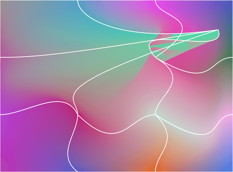
- Create a grid out of cubic Bezier curves (i.e., squiggly lines formed by a starting point, an end point, and two control points in between them). Each patch formed by four Bezier curves is called a Coons patch.
- Assign a color to each Bezier curve's endpoints.
- Subdivide every Coons patch into smaller Coons patches using De Casteljau's algorithm and an efficient algorithm for subdividing linear Coons surfaces, while linearly interpolating the assigned color for every new end-point.
- Once the original Coons patch is divided enough many times to reach suitably small sub-patches, paint the sub-patches on canvas using a color that's bilinearly interpolated from its corners' colors. For performance and simplicity, you can also just draw quadrilaterals instead of actual Coons patches since no one will notice if the quadrilaterals are small enough.
- Now we have a mesh gradient!
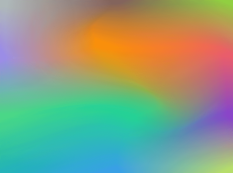
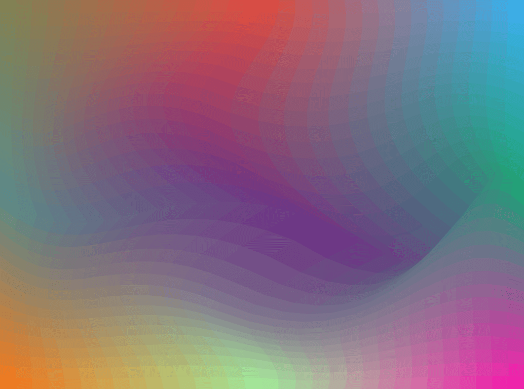
This was actually not too difficult to implement. The hardest part was figuring out the maths regarding subdivision (I'm not going to describe it here; the linked resources cover it pretty well), but once I got it, rendering the thing on a CanvasRenderingContext2D was pretty straightforward. With CanvasRenderingContext2D.bezierCurveTo it was easy to draw the bordering Bezier curves as well. As a bonus, by limiting the number of subdivisions, I could make the mesh gradient more retro-looking with a pixelated texture. All in all, this was starting to look pretty good!
As I was playing with my creation, I ran into problems: although rendering works nicely on low-poly versions where patches weren't subdivided too many times, the engine started to sputter on higher subdivision counts. Dragging control points was lagging and my laptop's fans started spinning like crazy. Performance this bad was simply unacceptable, so the first iteration wouldn't do.
Dipping My Toe In WebGL
To improve performance, I decided to try the other algorithm described in the blog post: Fast-Forward Differencing. Fast-Forward Differencing lets us render high-fidelity mesh gradients more efficiently than with high subdivision counts. The way it works is by drawing individual 1 pixel thick Bezier curves and then stacking them to form the full patch. Every Bezier curve's every point is derived from its earlier points.
After I implemented this, the performance of high-fidelity renders improved significantly, but it was still not snappy enough. To make it better, I needed to open my bag of tricks. Two options immediately came to mind:
- Find a faster algorithm (duh).
- Use the magic of WebGL shaders by offloading the heavy computations to it.
I had already invested plenty of time in the algorithms I had tried and didn't have a good lead on a better one, so I decided to reach for WebGL. I had never written any WebGL and didn't want to use a library like Three.js or Babylon.js, so I had to hit the books again.
I must admit my understanding of shaders was tenuous at best. I had dabbled with them during my uni studies 10 years ago when I took a course on computer graphics (by the great Jaakko Lehtinen), but my takeaway from that time was that shaders are black magic that can solve any performance related issue in the hands of a skilled coder. "I'm not half bad at coding", I thought to myself, "how hard can it be", I confidently assured myself of the challenge I was facing. Needless to say, I was in for some interesting lessons.
Disclaimer! I'm a total newbie when it comes to shaders, so what I've written below might be inaccurate or just a dumb way of doing things; please remember I'm still learning about this topic!
Armed with more enthusiasm than patience, I dove head first into writing all the necessary boilerplate to render something on a canvas using WebGL2 (WebGL2 Fundamentals was an excellent resource that I consulted a lot). I then realized that my plan wouldn't actually work quite as straightforwardly as I'd hoped: the way I had set up my code for either of my algorithms was more or less recursive, and that is not a very suitable approach with shaders. For all my shader newbies out there, here's an explanation why:
A simple GL setup uses two shaders: a vertex shader and a fragment shader. You give the shader program a bunch of vertices forming primitive shapes (triangles most commonly), which the vertex shader transforms into clip space, and the fragment shader provides color for every pixel in them. You then repeat this for as many times as you need, and you're done. However, there's a gotcha in here: the fragment shader runs the whole code for every pixel in every shape passed to it without saving state in between. So, if you have a recurring algorithm, let's say a Fibonacci sequence, to determine a pixel's color, it might look like something like this:
function getRGBAtPoint(pointIndex: number): [number, number, number] {
  let prevColor = 0;
  let color = 1;
  for (let i = 0; i < pointIndex; i++) {
    [prevColor, color] = [color, prevColor + color]
    color %= 255;
  }
  return [color, color, color];
}
On a CPU, you would get the color for each pixel in O(n) in one pass. However, in GPU you'll have to run that for every pixel in the area passed to fragment shader and the total complexity is O(n2). So, in order to leverage the parallel computing goods of GPUs in a smart manner, I had to set up things differently.
I first tried calculating each pixel's color in CPU, creating a texture out of them, and rendering it in WebGL. While that didn't solve the performance issues, it was a useful exercise in using textures in WebGL I guess; silver linings and all. I was struggling to come up with a better way to do it, but had a nagging feeling I was missing something. After letting it sit for a few days, I finally got it.
Barycentric Coordinates To The Rescue
I knew that of the two algorithms I had tried, Fast-Forward Differencing wouldn't work because it's recursive by nature. However, for patch subdivision I could get more creative. Up to this point, I was simply dividing the original patch into smaller subpatches and then using bilinear interpolation to find the color of that patch. To get a high fidelity drawing, the patch had to be divided many times to make each subpatch so small a naked eye couldn't distinguish where one ended and another started. I eventually realized that I can pass pretty coarse subpatches to the shaders and derive the color for every pixel within it by using barycentric coordinates. It works like this:
// Use barycentric coordinates to get the UV value of any point
vec2 getUV(vec2 point) {
  float EPSILON = 0.00000001;

  vec2 p1 = north_west_position;
  vec2 p2 = north_east_position;
  vec2 p3 = south_east_position;
  vec2 p4 = south_west_position;

  float d1 = length(point - p1);
  float d2 = length(point - p2);
  float d3 = length(point - p3);
  float d4 = length(point - p4);

  // Add epsilon to denominator to avoid dividing by zero.
  float w1 = 1.0 / (d1 + EPSILON);
  float w2 = 1.0 / (d2 + EPSILON);
  float w3 = 1.0 / (d3 + EPSILON);
  float w4 = 1.0 / (d4 + EPSILON);

  vec2 v1 = north_west_uv;
  vec2 v2 = north_east_uv;
  vec2 v3 = south_east_uv;
  vec2 v4 = south_west_uv;

  vec2 uv = (v1 * w1 + v2 * w2 + v3 * w3 + v4 * w4) / (w1 + w2 + w3 + w4);

  return uv;
}
UV coordinate is just a simple vec2 whose X and Y values are in range [0, 1]. When the patch's corner colors and the pixel's UV coordinates are known, we can use bilinear interpolation to get the properly blended color for the pixel, like so:
vec4 bilinearPixelInterpolation(vec2 uv) {
  vec4 color_top = mix(north_west_color, north_east_color, uv.x);
  vec4 color_bottom = mix(south_west_color, south_east_color, uv.x);

  return mix(color_top, color_bottom, uv.y);
}
After this revelation, my previous performance issues were gone: the app got snappy!
Adding Stuff In The Name Of Art
Now that the hard part was done, it was time to add some dials and toggles to make it more interesting. Adding selectors to change patch count was a given, as was implementing toggles to hide control points and Bezier curves. In addition to those, I added a switch to toggle between the retro tesselated look (which I really like!) and the more vivid high-resolution render; I also added a selector to control how many times we divide each patch to control the edginess of the curvature, and to control the size of the low-poly subpatches.
I also decided to implement support for color models other than RGB. My main motivation for this was sparked by an excellent blog post by Prasanna Mestha on how gradients appear in different color models. The RGB color model gets easily muddy and gray when sliding from one color to another, a problem which is solved with alternative color models like HSL. So, I implemented the color interpolation in HSL and Oklab color models, which yielded some interesting results.
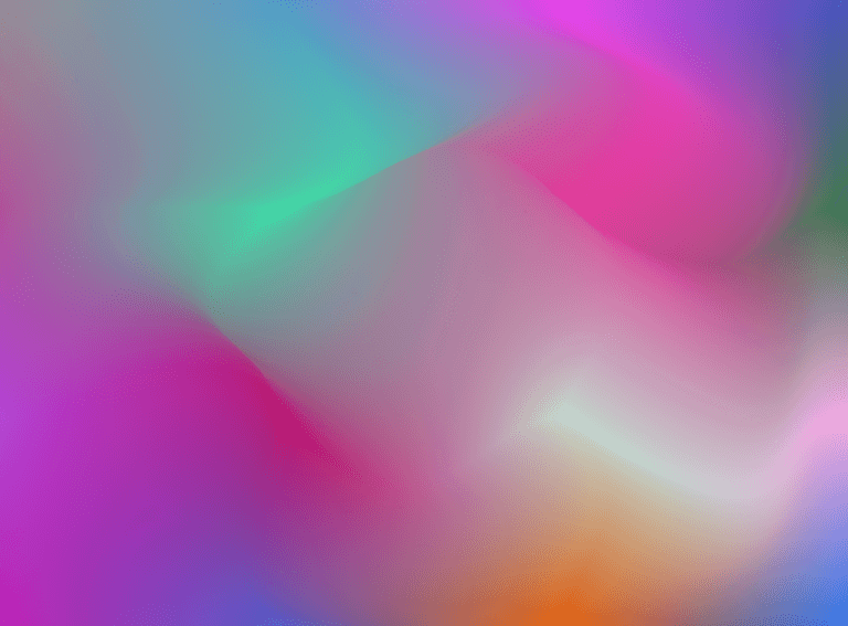
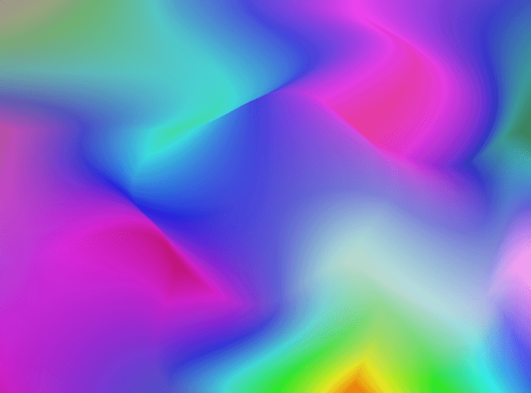
As you can see, the HSL color model is quite different from RGB and Oklab. While I actually like RGB the most out of these, it was fun to experiment with this.
At this point, I had already spent a few weekends on this project and wanted to wrap it up, but I also really wanted to see how it would look like with some random motion. So, instead of diving into the rabbit hole of how to best implement random motion, I asked Claude AI to write it for me. I was actually quite impressed with the output, even though I did have to clarify my vision over a few iterations; ultimately though it turned out real nice.
There are still a few glitches, e.g., in certain positions the patches can break down, but I think that's fine. I can make cool and warped mesh gradients despite it. Also, I might explore implementing bicubic interpolation instead of bilinear interpolation later, which could aid in fading patch borders.
And that's it! This was a fun project and I'm pretty happy with how it turned out.